zondag 29 januari 2017

RSP1 is replaced by RSP2 inside the Vasyljev


This heart transplantation was inevitable.

The images tell the story by itself!

Before the transplantation:

Both the Airspy Mini and the RSP1 on board.

.... and how it changed to Vasyljev 2.0


Removed the back pane


The RSP1 removed and the RSP2 on its position


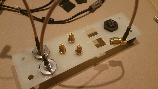
Preparing the new back pane


Almost ready, thanks to the Dremel


The Hi-Z terminals in place


Back pane

Populating the back pane


New situation

The Hi-Z interconnection is ready


Back pane - once again 


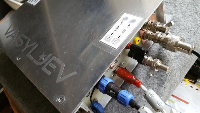
With banana to BNC adapter


Earth plate now connected to BNC terminals becaue floating inputs were a bit noisier


Operating the Vasyljev 2.0


CAT control implemented
A wire antenna that can be connected to the Hi-Z input directly


donderdag 1 september 2016

Finally: AirSpy and SDRplay under one hood

Lately I took my aluminium-cased multi-SDR thing to the next level by adding the AirSpy Mini. Now it has two SDR receivers under one hood. I decided to go for the AirSpy mini because I want to use the rig in the field with a very light-weight 11.6" duocore laptop. It works pretty well @6MSPS and very well @3MSPS. So I am satisfied.


I did some modifications as well. Originally, the USB-cables entered the enclosure through a cable gland. I wanted the cables to be left in one piece, just to keep the number of connectors in the data chain as low as possible. However, an enclosure with cables that are always connected, is not so easy to handle, looks stupid and one day the wires in the cable will break due to metal fatigue. So I mounted the best USB receptacles I could find (Amphenol, mil grade, phosphor bronze...). I works perfectly, no issues found yet.


One day I will finish the project by adding the third module: a HF converter for the AirSpy mini. I am torn between the SV1AFN design and the SpyVerter. It will probably take half a year of indecision before anything happens.


I clamped the AirSpy Mini to the aluminium casing to keep it cool.

A picture tells more than 1000 words.


dinsdag 28 juni 2016

The SDRplay heart beats inside. What's up next?


[See older posts for project step-by-step here]

The thing, with its SDRplay heart beating inside, works like a champ. No USB noise at all, only plain atmospheric noise and a few restless electrons in all (semi)conductors. Feels like analogue times.

The RSP is slightly professionalized. The unit is mostly powered from a cheap 10000 mAh USB power bank which guarantees days of receiving fun.

The next small big thing on the schedule is the implantation (implementation by soldering) of a second heart, the Airspy R2 and a HF converter. I have not yet decided which HF converter; The choice is between the Spyverter and the SV1AFN converter. Both have their own architectures - hence their own advantages and disadvantages. If you have any suggestions, please let me know.

The thing, in working state

Before I do the Airspy & converter implantation, I will prepare a few other small accessories.

First I will assemble an external, ruggedized LNA unit which can be powered by either phantom or external power. I tend to the LNA4ALL. If you have any suggestions for other LNA's, please let me know.


Copyright LNA4ALL


The second accessory is a FM broadcast band rejection filter. I have ordered the F1JKY filter which is a optimized Chebyschev 7-th order filter with high quality components.

 
Copyright F1JKY

The back plate of my SDR is now equipped with a M6 earth rod made of stainless steel. That can be very useful for HF listening.


Earth rod


I will keep you informed.
donderdag 12 mei 2016

Operational with RF-Systems preselector and USB powerbank

Today I did some tests with powering the unit with a 5V power bank. The 5V lead uses the same connector on the back panel, which has 4 poles, two for 12V and two for 5V. So one power supply can be used at a time.

Also the RF-Systems P-3 preselector works great in combination with the SDRplay. An EF-SWL longwire for RX only was used.

The EF-SWL longwire is a rugged, very portable HF antenna that yields stunning results. Highly recommended!

[See the EHAM user reviews here. It gets a solid 5.0 rating after more than 40 reviews - there is no other item with a comparable rating.]


On the left the 10400 mAh power bank. On top the HF preselector.

Preselector on top.

woensdag 11 mei 2016

First stage now finished. See pictures.

My double-SDR is now halfway finished: It is operational with the SDRplay only. After summer, I will add the next two modules, the AirSpy and some converter, either the Spyverter or the SV1AFN - have not decided yet.

A picture tells more than 1000 words, so here is the story:


Testing indicator LEDs behind diffusor, enclosure not ready yet

Rubber feet

Velcro strip for SDRplay

Provisional sticker

Serious nuts & bolts

USB cable is led into case without connector

Back panel, one RF-connector still missing (for HF converter input)

Paper template to check if things will fit


I will summarize the concept of my project once again. I consider the SDRplay and the AirSpy as modules, not as devices. I want to have two SDR's under one hood, so I can employ either receiver in the appropriate situation. No module can be fed by the USB host at all. There is a separate 13,8V input (batteries, linear power supplies) and a separate 5V input (cheap power banks).

dinsdag 26 april 2016

One Year Later: let's start building

After some "time consuming considerations" (one year!) about the logic around the RF modules, such as DC feed lines, switches, earthing, ground loops, common mode line chokes, decoupling C's, feed-throughs and much more, I finally started to assemble the enclosure that I designed earlier.


The enclosure in a raw state - plastic protection, no panel holes yet. All
Aluminium plates and profiles are 2 mm thick and all nuts and bolts are stainless steel.


About logic: There will be one DC connector with 5 poles. Three different DC cords will be assembled. Of course, you can use one at a time, for different purposes. Cable 1 is for 12V DC sources. The 12 V DC will be lead to the internal linear 7805 converter. In this case, you can run either one of the receivers, or both simultaneously. Cable 2 is for 5 V DC sources which feed either one of the receivers - running two receivers is not enabled. Cable 3 is also for 5 V DC sources, but by short-cutting two poles of the chassis jack, running both receivers simultaneously is enabled. The latter is meant for using 5 V power supplies that are powerful enough to feed both receivers simultaneously.


Some switching and feeding logic


But as always: I may as well change everything while building the thing. And as long as it is a hobby project, everything is allowed!

Next step will be: A copper plated epoxy carrier board will be placed onto the bottom plate of the enclosure; This will be the underlayment for all circuitry. This underlayment will be galvanically connected to the enclosure at one single earth point.


Some parts that I may need


Waiting to be mounted...

Panel cut-out sketches. Has changed a zillion times already.
And no boss who complains! Hobbies are a sanctuary.